Here is a quick writeup of the protocol for the iKettle taken from my Google+ post earlier this month. This protocol allows you to write your own software to control your iKettle or get notifications from it, so you can integrate it into your desktop or existing home automation system.
The iKettle is advertised as the first wifi kettle, available in UK since February 2014. I bought mine on pre-order back in October 2013. When you first turn on the kettle it acts as a wifi hotspot and they supply an app for Android and iPhone that reconfigures the kettle to then connect to your local wifi hotspot instead. The app then communicates with the kettle on your local network enabling you to turn it on, set some temperature options, and get notification when it has boiled.
Once connected to your local network the device responds to ping requests and listens on two tcp ports, 23 and 2000. The wifi connectivity is enabled by a third party serial to wifi interface board and it responds similar to a HLK-WIFI-M03. Port 23 is used to configure the wifi board itself (to tell it what network to connect to and so on). Port 2000 is passed through to the processor in the iKettle to handle the main interface to the kettle.
Port 2000, main kettle interface
The iKettle wifi interface listens on tcp port 2000; all devices that connect to port 2000 share the same interface and therefore receive the same messages. The specification for the wifi serial board state that the device can only handle a few connections to this port at a time. The iKettle app also uses this port to do the initial discovery of the kettle on your network.Discovery
Sending the string "HELLOKETTLE\n" to port 2000 will return with "HELLOAPP\n". You can use this to check you are talking to a kettle (and if the kettle has moved addresses due to dhcp you could scan the entire local network looking for devices that respond in this way. You might receive other HELLOAPP commands at later points as other apps on the network connect to the kettle.Initial Status
Once connected you need to figure out if the kettle is currently doing anything as you will have missed any previous status messages. To do this you send the string "get sys status\n". The kettle will respond with the string "sys status key=\n" or "sys status key=X\n" where X is a single character. bitfields in character X tell you what buttons are currently active:| Bit 6 | Bit 5 | Bit 4 | Bit 3 | Bit 2 | Bit 1 |
| 100C | 95C | 80C | 65C | Warm | On |
So, for example if you receive "sys status key=!" then buttons "100C" and "On" are currently active (and the kettle is therefore turned on and heating up to 100C).
Status messages
As the state of the kettle changes, either by someone pushing the physical button on the unit, using an app, or sending the command directly you will get async status messages. Note that although the status messages start with "0x" they are not really hex. Here are all the messages you could see:
| sys status 0x100 | 100C selected |
| sys status 0x95 | 95C selected |
| sys status 0x80 | 80C selected |
| sys status 0x100 | 65C selected |
| sys status 0x11 | Warm selected |
| sys status 0x10 | Warm has ended |
| sys status 0x5 | Turned on |
| sys status 0x0 | Turned off |
| sys status 0x8005 | Warm length is 5 minutes |
| sys status 0x8010 | Warm length is 10 minutes |
| sys status 0x8020 | Warm length is 20 minutes |
| sys status 0x3 | Reached temperature |
| sys status 0x2 | Problem (boiled dry?) |
| sys status 0x1 | Kettle was removed (whilst on) |
You can receive multiple status messages given one action, for example if you turn the kettle on you should get a "sys status 0x5" and a "sys status 0x100" showing the "on" and "100C" buttons are selected. When the kettle boils and turns off you'd get a "sys status 0x3" to notify you it boiled, followed by a "sys status 0x0" to indicate all the buttons are now off.
Sending an action
To send an action to the kettle you send one or more action messages corresponding to the physical keys on the unit. After sending an action you'll get status messages to confirm them.
| set sys output 0x80 | Select 100C button |
| set sys output 0x2 | Select 95C button |
| set sys output 0x4000 | Select 80C button |
| set sys output 0x200 | Select 65C button |
| set sys output 0x8 | Select Warm button |
| set sys output 0x8005 | Warm option is 5 mins |
| set sys output 0x8010 | Warm option is 10 mins |
| set sys output 0x8020 | Warm option is 20 mins |
| set sys output 0x4 | Select On button |
| set sys output 0x0 | Turn off |
Port 23, wifi interface
The user manual for this document is available online, so no need to repeat the document here. The iKettle uses the device with the default password of "000000" and disables the web interface.If you're interested in looking at the web interface you can enable it by connecting to port 23 using telnet or nc, entering the password, then issuing the commands "AT+WEBS=1\n" then "AT+PMTF\n" then "AT+Z\n" and then you can open up a webserver on port 80 of the kettle and change or review the settings. I would not recommend you mess around with this interface, you could easily break the iKettle in a way that you can't easily fix. The interface gives you the option of uploading new firmware, but if you do this you could get into a state where the kettle processor can't correctly configure the interface and you're left with a broken kettle. Also the firmware is just for the wifi serial interface, not for the kettle control (the port 2000 stuff above), so there probably isn't much point.
Missing functions
The kettle processor knows the temperature but it doesn't expose that in any status message. I did try brute forcing the port 2000 interface using combinations of words in the dictionary, but I found no hidden features (and the folks behind the kettle confirmed there is no temperature read out). This is a shame since you could combine the temperature reading with time and figure out how full the kettle is whilst it is heating up. Hopefully they'll address this in a future revision.Security Implications
The iKettle is designed to be contacted only through the local network - you don't want to be port forwarding to it through your firewall for example because the wifi serial interface is easily crashed by too many connections or bad packets. If you have access to a local network on which there is an iKettle you can certainly cause mischief by boiling the kettle, resetting it to factory settings, and probably even bricking it forever. However the cleverly designed segmentation between the kettle control and wifi interface means it's pretty unlikely you can do something more serious like overiding safety (i.e. keeping the kettle element on until something physically breaks).
"Before" and "After" video:
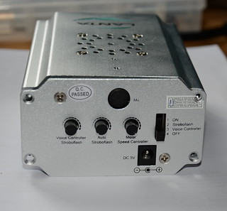
We were looking for a cheap laser lighting effect for our weekend parties and saw one that looked impressive, the Lanta Quasar Buster 2, and for only £30 new. The unit has both a red and green laser and and a nice moving effect that looks like the beams splits up and recombine again. It promised "sound activation" and we thought that meant it would do some clever sound to light effect, but it really does mean sound activation and just turns itself on when it hears a sound, then off again when it's silent. So out of the box the laser has three modes; the first lets you just set the speed of the effect with the lasers constantly on, the second strobes the lasers on and off to a speed you can set, and the third is the usless sound activation mode.
Warrany void if removed. I didn't technically "remove" the sticker though.
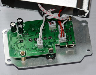
Opening the unit showed that it was easily hackable; all the connections to the control panel were via connectors. One connector provides +5v to the cooling fan, another +5v to a separate board that handles powering the two lasers, another connects to the motor the turns the optics to produce the burst effect, and the final one has a logic level signal to tell the laser power board if the lasers should be on or off.
Since the laser power board is completely separate we can just replace this control panel with one of our own and then we can control the laser on/off and the speed of the motor (actually we could control the direction too but it doesn't really make the effect look any better so I leave it as one direction). And we can always swap the original board back in the future.
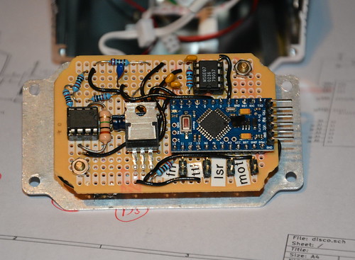
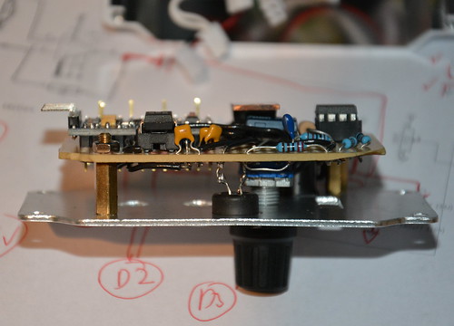
My new control board comprises of an Arduino pro mini compatible board, a rotary encoder for setting the mode and levels, a mic with simple opamp preamp, and a MSGEQ7 chip to do all the hard work of analysing the levels of various frequencies. The optics motor is now simply driven using a PWM output via a MOSFET I had spare.
Rough source and circuit diagram are available from github; some components don't have values if it doesn't really matter and others (like the MOSFET) can be changed as I just used things I happened to have in my component boxes. I'm still playing with different effects in software to see what works best.


